
“Electro-chemical and electro-mechanical apparatus for the display of illuminated messages”
Imaginary:
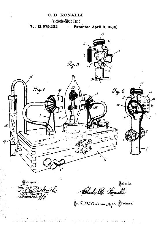
This device was invented, designed, and built by the eccentric and reclusive Dr. Charles D. Ronalli in the late eight-teen hundreds. Click on the following links to see Dr. Ronalli’s original patent drawings and descriptions!
Victorio-Nixie Patent Diagrams
Victorio-Nixie Patent Description
Victorio-Nixie Patent Description (alternate download location)
Real (documents):
Well, first off, both of the above documents are (of course) completely fake. This was accomplished using this actual patent as a template, then changing and inserting things using a little digital magic.
Since I lack the illustrative abilities to actually draw the diagrams, I had to find a way to cheat. I started out by performing these steps on the photos I had taken of the device, but the results looked more like a Xeroxed photo than a patent drawing. To fix this, I printed the results out and traced the parts I wanted in pencil. Once they looked the way i wanted, i scanned them back in and used Photoshop to darken the lines.
I used MS Paint to do most of the document modification, because I find it better suited to that sort of basic manipulation than Photoshop. Besides replacing the images, I also wanted to change the inventor’s name, hometown, and signature, as well as the patent number and the date it was filed/issued to somethign totally fictional. This was all done by rearranging the letters and numbers that were already in the document to preserve the original look as much as possible–even the signature! The body text of the abstract was not done this way (I’m not that dedicated), but instead typed up in MS Word–with the edited header pasted in. The style of the text was based off of that used in Nikola Tesla’s patents.
Real (device):
This device is really a (heavily) modified persistence-of-vision toy. This toy was a pen i picked up at the local pharmacy (Walgreen’s) with a spinning head that displayed whatever message you programmed in. It was only $5.00, so i picked up a couple and let my imagination fly. There’s just something about POV toys that I can’t seem to say “no” to!
The most difficult and time consuming task involved in this build was constructing the “Emitter Stalk”. In the original pen, the head was was only .5in above the motor–as opposed to the two-inch tube it now sits atop. Extending this proved to be far more difficult than i thought. There are so many variables to keep in mind when dealing with a spinning object–especially when said object has to maintain 3 separate electrical contacts with a stationary platform! On the back of the device–next to the power jack–there’s a potentiometer that controls the motor’s speed. I like the flickery way it looks when it’s running slowly, the motor’s not powerful enough to to actually get it moving at that lower voltage. With the pot., i can start it fast then ramp it down once it gets going.
The glass bulb that covers this contraption is a hollowed out GE Bent-Tip chandelier bulb. The instructions I found on-line for hollowing out bulbs didn’t apply to bulbs like this, so i came up with my own method. It worked surprisingly well, so I’ll post instructions later.
The bubble tube came from one of these. I got a set of 7 for like $3US at an after-Christmas sale. Naturally they wouldn’t do as-is, so I *carefully* Dremeled off the plastic base and bulb, leaving only the tube. Normally a 120v incandescent bulb provides both the heat and light necessary, but i needed something lower voltage and easier to conceal. As you see in one of the pictures, there is a 33ohm resistor and an LED inside the new brass base. There’s also a second LED in the top brass tube to give a more even light.
It was really just trial and error to find a resistor value that would get hot enough, but not too hot. I don’t have any way to actually measure it, but it’s cooler than a hot glue gun so i’d estimate it at around 150F. I’m SURE there’s a better (and safer) way to do this than running 6v directly through a low-level resistor, but hey; it works. I’ve let it run for days straight and it seems pretty stable, so i guess it’s good. The resistor is a bit, er, “browner” than before though…
The device is controlled through the use of the the lever and the button on the right-hand side of the box. The lever toggles through the characters; the button selects your choice. Holding the button down saves the message and puts it into display mode. Once in this mode, pressing the button scrolls through the 4 possible messages. The device is powered on by turning the key on the front clockwise, as if you were winding an alarm clock. Special thanks to Eurich Clock World of Dearborn, MI for donating the wonderful key!
The magnets are actually real, however their function is purely aesthetic in this machine. They were from a pack of novelty refrigerator/locker magnets that I acquired some time ago and had been dying to use for something. They’re incredibly weak, so they’re not much good for anything real 🙂
Here’s the device in action:
For more info on the pen, check out the following links. I couldn’t find it for sale anywhere, other than these wholesalers who only sell ’em by the crate. They may be of help though, if you’re desperate.
Cost: $20US
Time: About 10 hours for the device, 3 hours for the documents
Tools: Basic hand tools, Dremel, drill w/ press, soldering iron, and JB Weld
Approx. Date of Completion: January 2007

do you have a job??
I’d totally buy one of those. XD
Beautiful !
Thanks for another magnificent post. The place else could anybody get that type of information in such a perfect method of writing? I have a presentation next week, and I am on the search for such information.