I’ve started working on something that is somewhere in the intersection of “sci-fi prop replica” and “useful tool”:
a functional tricorder from Star Trek: The Next Generation. Introductory details and a video below.
Design goals:
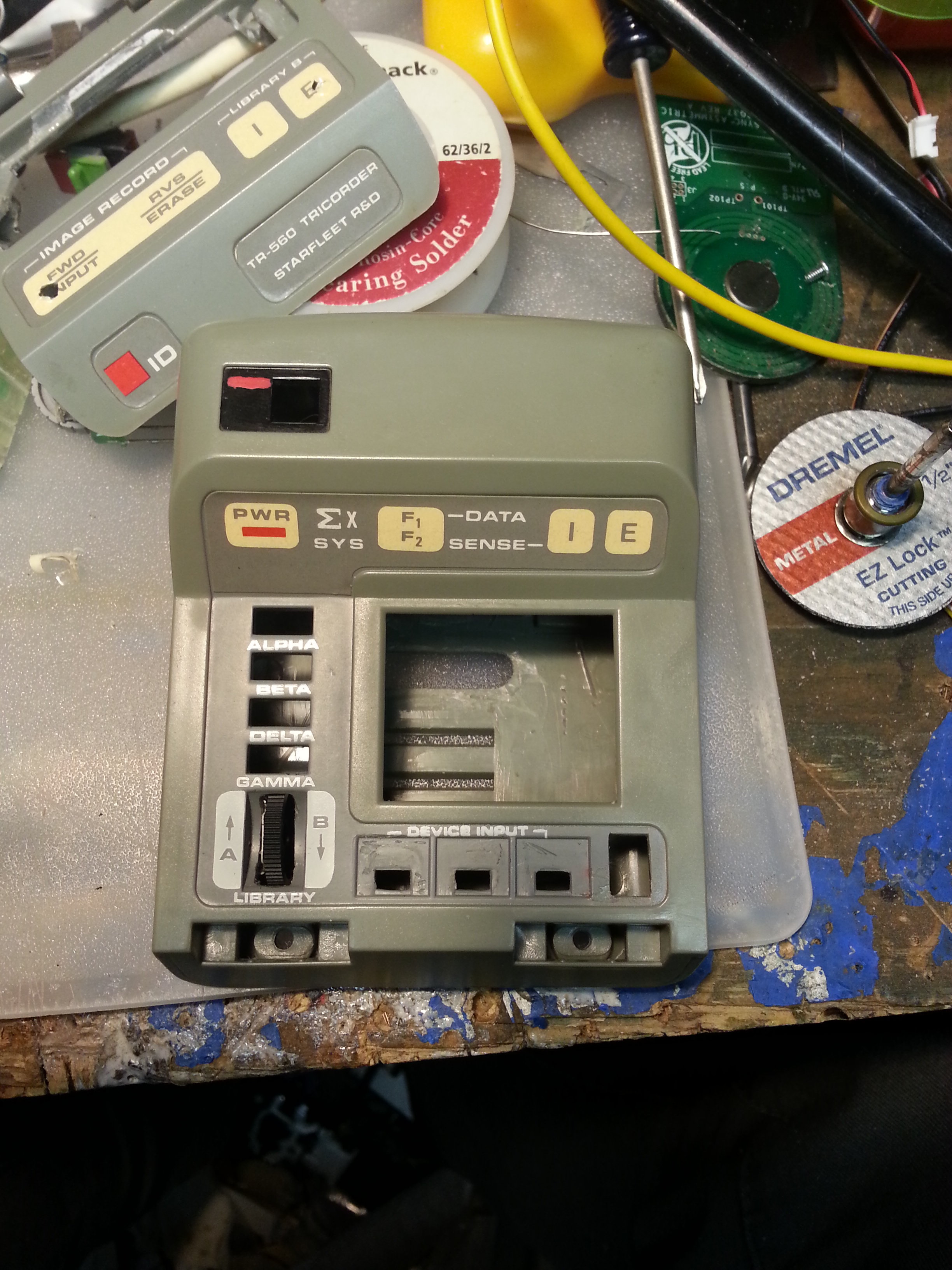
- Using a Playmates toy tricorder, create a reasonably good replica of the tricorders used on screen.
- Make it able to collect useful measurements from the outside world
- Use only non-contact sensors as a “real” one would
- Use sensors that are not already available in my smartphone
- Low cost
There are many projects out there attempting to build devices that function like a real-life tricorder (this, this, and others), and many more that seek to replicate (ahem) the film props for display and cosplay (search “tricorder” on theRPF.com). I believe my project is fairly unique in trying to do both to some extent.
One thing I’m doing differently from the folks building the other functional ones is my sensor selection. When I started thinking about this project a few months ago, my list of sensors and functions was pages long. For cost and size restrictions, it was clear I had to cut down. The first rule I imposed on myself was to avoid redundancies with my phone. I can already measure acceleration, motion, audio amplitude and frequency, and barometric pressure with the dedicated sensors in my Android device with very useful accuracy, and heart rate, colorimitry, and other things with reasonable quality through its camera. Accelerometer/gyro chips are cool, but I thought it a waste to include them at this point.
This still left me with a long list of things that would be hard to implement, mostly related to electrical measurements. I still plan to build something similar that combines a DMM, ‘scope, DC source, etc in a pocket device, but it was all getting to be too much for this project. Thus the rule to only include non-contact sensors was born. Thermocouple? Boring! IR sensor that reads the temperature of an object just by looking at it? Star Treky and awesome! Almost as cheap and easy too.
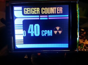
I’ll go more into the hardware in later posts, but for now please enjoy a quick video of my “development board” running the basic GUI code. (Yes, that’s a cutting board from Dollar Tree)
The horizontal row of LEDs are for the mode buttons (GEO MET BIO on a stock one), and the vertical column is for that space to the right of those buttons. As shown, these indicate which of the nine sensor modes are engaged.
No sensors attached to the Arduino in this test, just capacitive buttons (Seeed Studio Q-Touch), function LEDs, and sound board (JQ6500). The LCD is a Digole unit, which is very nice for beginners.
Pay no attention to how the colors on the LCD look on camera.The image at the top of this article is a better representation, but still not great. Better stuff to come…

Nice job. I am experimenting with Arduino and LCD screens myself for use in my tricorder replicas. Let me know if there is any way I can help you with your project. – Gerry “GMProps”
Hi I am doing a similar( but different! ) project using a clone ‘touch screen ‘ MP4 player to record and store LCARS screens , my difficulty is making it play directly on start up without going through the startup and mode select screens. Any help or advice welcome , as well as that I am recreating all the graphic led’s from originals and trying to colour match , I will be displaying my finished results within the next week or so, so far so good ! Anything I can do to help just drop a line , been building and restoring props for over 40 years .
Jonnyb
download zombie roadkill 3d hack
Functional Tricorder, Part 1 | Jake of All Trades
movies to watch and download free
Functional Tricorder, Part 1 | Jake of All Trades